

ArcGIS Pro and Blender can be used alongside each other to create some truly stunning 3d hillshade renders. In this tutorial, we’ll give you a quick overview of the process. We don’t go into great detail about the process or why things are setup in certain ways. For a more in-depth overview, check out this blog post.
A lot of the time of this workflow is setting up Blender. But once setup the way you like, it is much faster to create new renders. If you have already setup Blender and just want to skip to repeating the process, check out this blog.
Get your elevation data from ArcGIS Pro and the Living Atlas
Open a new project in ArcGIS Pro. Open a map, and zoom to your area of interest. Consider your projection carefully, as it won’t be able to be changed. Create a polygon feature class in the projection you chose, and draw a bounding box around your area of interest. Then add the terrain layer from the Living Atlas.

An area of interest polygon over the Mediterranean, with the Living Atlas terrain layer underneath.
Next, export the terrain using the Export Raster tool.
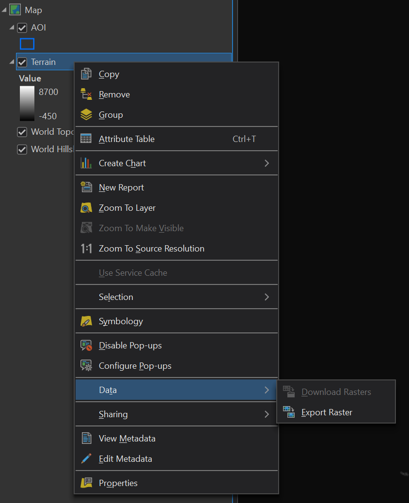
The ArcGIS Pro Export Raster tool.
Carefully consider your export settings. Key things to consider are the output format (TIFF), the clipping geometry (which is your area of interest polygon) and the raster size. When exporting from the Living Atlas, you are restricted to a raster size of 5000 x 5000, so we will choose that as a maximum.

Raster export settings.
This isn’t the final raster we will use. Now we have to fill areas that have no value (like the ocean). To do this, we will use the raster calculator. Set it up as follows:

Then we want to stretch the values of the raster using the raster calculator:
(“rasterName” – Lowest Value) ÷ (Highest Value – Lowest Value) * 65,535The lowest and highest values of the raster will be shown in the contents pane of ArcGIS Pro.
Finally, resave the raster:
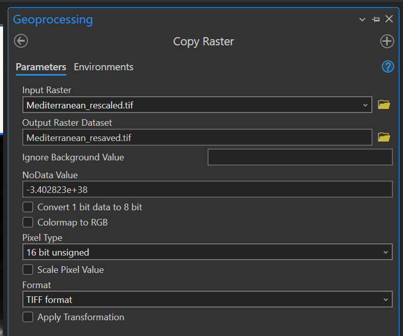
Final output settings for the raster before it goes into Blender.
We’re finished with ArcGIS Pro for now.
Setup Blender
Now, download and install Blender. Open it up and change the Render settings to “Cycles”. This is in the camera icon to the right.
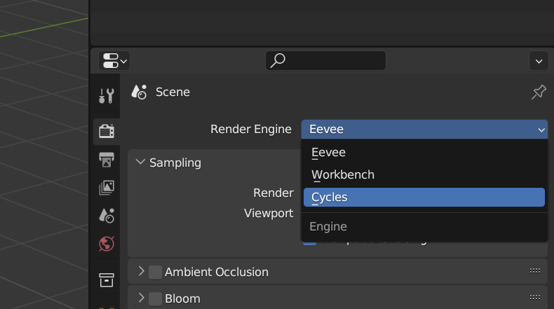
Changing render settings in Blender to Cycles.
Then change Feature Set to “Experimental”.
A cube will be in the view port. Select it and hit delete. Save your project.
Setup the plane
On the keyboard, hold shift and press A. Create a plane.
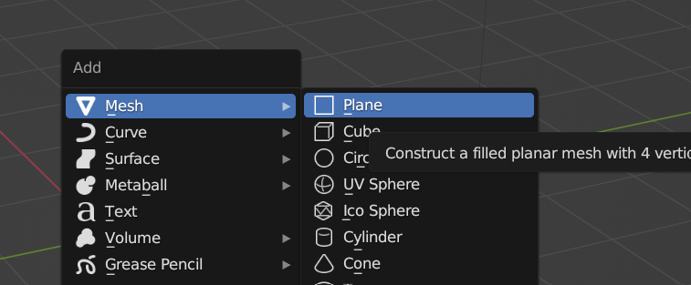
Creating a plane in Blender.

How the plane will look when first added.
Now you need to change the size of the plane to match the size of the raster that was saved. Look up the properties of the tiff:

Dimensions of the tiff we exported.
Click on the plane in Blender, and then the orange properties box on the right hand side. Change the scale settings to match the dimensions of the raster (divide by 1000 to ensure it fits on the screen).
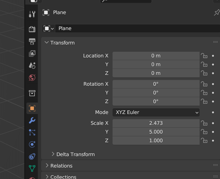
The plane scaled to match the raster dimensions.
Setup the material
This specifies how light will react when it hits the surface. With the plane highlighted, select the ball icon on the right hand side and click ‘New’. Leave most settings default, except change roughness to 1, and specular to 0.

Meterial settings.
Further down in these properties, expand Settings, and set Displacement to “Displacement Only:”.

Displacement settings.
While we’re at it, we’ll also tweak one more setting. With the plane selected, click on the blue wrench on the right hand side, click Add Modifier, and then Subdivision Surface.

Then change the Subdivision type from Catmull-Clark to Simple.
Shade editor
Now change from the 3D Viewport to the shade editor.

How to access the shade editor.
Add a texture to the shade editor by clicking Add > Texture > Image Texture. Then place the box, click open and select the raster image that was prepared earlier.
Next add Vector Displacement (Add > Vector > Displacement).
Then change the following settings:
Change the color space to “Linear”.
Change Image Texture node from “Repeat” to “Extend”.
Check that Roughness is 1, and Specular is 0.
Change the Displacement scale. A good starting point is 0.3, but I will use 0.4 for this example. Think of this as the vertical exaggeration of the terrain.
Connect the boxes in the shade editor together as shown below.
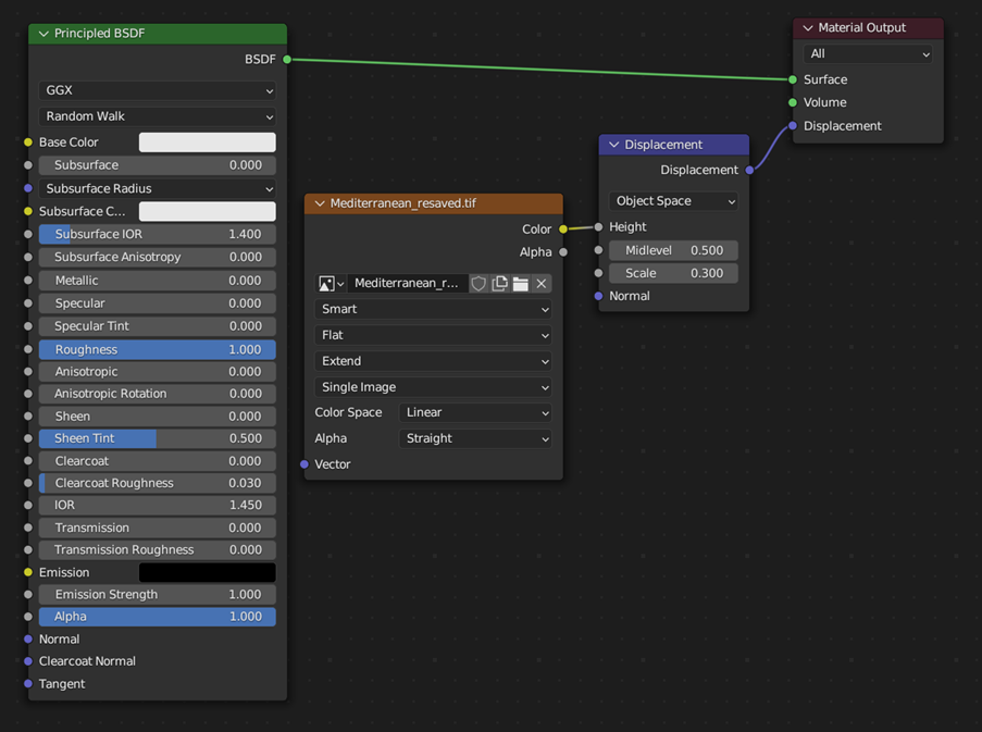
Final Shade Editor settings.
Setup the camera
Go back into the 3D Viewport. Click the camera and go to View > Cameras > Active Camera. This will show you what the camera is looking at. It needs to be looking top down on the plane.
With the camera still selected, go to the properties and change the camera location to x=0, y=0 and z =3. Then the rotation to x=0, y=0 and z=0.

Camera location and rotation settings.
If you look at the cameras view again (View > Cameras > Active Camera), you will see it is in the right location, but has the wrong aspect ratio. To get that right, change the Scale properties shown above to match the aspect ratio of your image. For our example, it is x=5, y=2.473 and z=1 (this matches the dimensions of our tiff, divided by 1000).
Now select the icon that looks like a printer, printing an image. In here, you need to set the resolution to equal that of your raster.
Then select the movie icon and change the lens type from Persepctive to “Orthographic”. And finally, set the orthographic scale to twice the largest dimension of your raster.

Changing the lens from Perspective to Orthographic.
Setup the light source
In the 3D Viewport, click the light, and edit its properties.
Change the light source properties (light bulb icon) to sun and strength to 5.
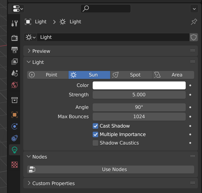
Changing the light to a sun.
Then go to the object properties (orange box icon) and change the rotation to x=0, y=45 and z=135.

Light rotation settings
The Y value changes the suns position in the sky. A value closer to 90 degrees would be lower in the sky (afternoon). I will set it to 60 to produce more shadows.
Render
Remember to save.
Go to Render > Render Image. A new window will open where the image will be produced. Give it time.
Once complete, select Image > Save. Save as a tiff.

The final render from Blender.
Add the render to ArcGIS Pro
The image has lost geographic information. So you now need to add it to your map and georeference it.
Imagery tab > Georeference.
If you are still zoomed in on your area of interest, with the georeferencing tab open, click “Fit to Display”. It will plonk it down in the middle.

Georeferencing after “Fit to Display” is selected.
Then add control points to the corners to link it to the polygon you created earlier.

Adding control points to the corners.
Repeat for each corner and select save and close the georeferencing pane.
Change the basemap to imagery.

The render after georeferencing.
Add an “Overlay” blend mode to the render. Adjust any other display settings you like such as the stretch type and transparency. We have selected a stretch type of none.

The render after an overlay blend mode is applied and a stretch type of none.
Then create a layout and export as you like.
Repeating the process
As mentioned, once setup, you can utilise the same Blender project for different images. Refer to this blog for info. The short version is:
Export a new terrain dataset from ArcGIS Pro.
Change the dimensions of the plane in Blender to match the export.
Edit the output dimensions.
Edit the cameras scale.
Choose a heightmap file.
Export from Blender.
Georeference in ArcGIS Pro and finalise visual settings.
Happy map making!